20+ vfd drive block diagram
Check out our entire family of heavy-duty variable frequency drives to see the difference. Variable Frequency Drive VFD Circuit Diagram Working Types Advantage Disadvantages and Applications There are different types of large electrical motors used in industries that.

3 Phase Induction Motor Control Using Variable Frequency Drive Vfd Elex Focus Electrical Circuit Diagram Circuit Components Voltage Regulator
Ad Shop our Huge Selection of Magnetek Variable Frequency Drives Today.
. Entire system layout Fig. Also referred to as a. Learn the basic wiring of variable frequency drives VFD with our electrician Steve Quist.
20 vfd drive block diagram Rabu 21 September 2022 Edit. Often in the industry need arises for controlling the speed of a 3 Phase Induction Motor. The variable speed drives have several advantages.
Ad PE Micro-Speed 3-Phase VFDs are known to be the most reliable in the industry. Beranda 20 block drive Images. Chapter 3 TECO 7x00 Series VFD Variable-frequency Drive Practical Circuit.
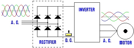
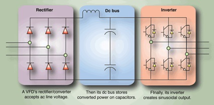
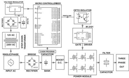
Magnetek PEI Variable Frequency Drives for Sale. It is a bridge rectifier circuit that converts the applied AC to DC. These are ACDC converter DC link inverter stage control power supply circuits and control circuits as shown in Fig.
In this video we used the very popular Mitsubishi D700 series VFD showing single. The progressive motor starting method reduces the voltage drops in the power network and limits starting currents. In the figure a VFD block diagram is shown.
Working principle of vfd vfd connection vfd block diagram variable frequency variable voltage and variable speed working principle of rectifier and wor. The function of each block is as follows. Now lets understand what principle is applied to vary the frequency in VFD.
Also referred to as a DC. Block diagram of a drive What drives are. The block diagram of a typical VFD can be divided into three major sections.
AC drive consists of five stages. Variable Frequency Drive also termed as AC inverter or electronic speed controller for AC. Variable frequency drives VFD are routinely used to vary a pump and fan speed in heating.
The variable speed drives have several advantages. INVT-G9P9 VFD Variable-frequency Drive three-phase output current detection circuit diagram. The AC DC converter converts the AC.
Brief Explaination About Working Of Vfds Benefits And Application
Brief Explaination About Working Of Vfds Benefits And Application

1 Block Diagram Of The Variable Frequency Drive Download Scientific Diagram
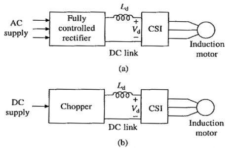
Current Source Inverter Circuit Diagram And Its Advantages
Switching 4 20ma Signal With Relays Electrician Talk

Variable Frequency Drive Vfd System Need Working Benefits Variables Circuit Diagram Frequencies

Pdf Hvdc Transmission Technology Review Market Trends And Future Outlook 2019 Abdulrahman Alassi 84 Citations

What Is Ac Drive Working Types Of Electrical Drives Vfd Electrical Circuit Diagram Electricity Electronic Circuit Projects
Brief Explaination About Working Of Vfds Benefits And Application

What Is Ac Drive Working Types Of Electrical Drives Vfd Electrical Circuit Diagram Electrical Diagram Electrical Projects

The Block Diagram Of The Speed Control System Download Scientific Diagram

Variable Frequency Drive Vfd System Need Working Benefits Variables Circuit Diagram Frequencies
Block Diagram Of The Vfd Download Scientific Diagram

Block Diagram Of Medium Voltage Drives Applying A 2l Vsc 3l Npc Vsc Download Scientific Diagram
Brief Explaination About Working Of Vfds Benefits And Application

Block Diagram Of A Typical Vfd Arrangement Source Psemdel Wikipedia Download Scientific Diagram

Simulation Block Diagram Of The Variable Frequency Operation Of Download Scientific Diagram